The government has declared that no new petrol- or diesel-fuelled vehicles will be sold in the UK after 2030 and that the sale of new hybrid vehicles must cease by 2035. It has also been reported that legislation is to be introduced requiring electric vehicle (EV) charging points to be provided in all new-build homes in the UK, possibly as soon as 2022. In the light of these developments, it is clear that the already fast-growing demand for EV charging points will see further dramatic and sustained growth over coming years.
For electrical contractors, this offers an enormously important business opportunity but, to capitalise on this, they must clearly understand the regulatory and technical requirements associated with the installation of EV charging points. For the most part, these are contained in BS7671:2018 – The IET Wiring Regulations. Section 722 of these regulations, which was updated as part of Amendment 1 issued in 2020, applies specifically to EV charging points.
When considering the installation of charging points, contractors must first determine exactly what is required. Charging arrangements are divided into four ‘modes’. The simplest, Mode 1, uses standard socket outlets and also uses ordinary power and protective earth (PE) conductors between the AC supply and the vehicle. This mode is rarely adopted for new installations. Mode 2 provides charging currents up to 10 A and is similar to Mode 1 except that it adds a control pilot function and a system of protection against electric shock.
Mode 3 uses a dedicated charger – more formally, an Electrical Vehicle Supply Equipment (EVSE) – with integral control and monitoring. Like Mode 1 and Mode 2 installations, Mode 3 systems supply AC to the vehicle but are typically capable of providing much higher charging currents. This means that a three-phase supply may be needed. Mode 4 chargers supply DC to the vehicle and are capable of providing the very high currents needed for rapid charging. They are found mostly in public locations such as service stations and public car parks.
Having determined the type, rating and number of chargers required, the contractor’s next step is to examine – and verify – the supply infrastructure associated with the charger or chargers. It is essential to consider the voltage, frequency, number of phases and maximum demand, and to determine whether the existing infrastructure, including switchgear and cabling, has sufficient capacity to supply the additional load. Metering may also need to be considered, especially if the charging point is accessible to more than one user. Finally, it is essential to verify that the earthing and bonding arrangements are adequate to ensure safety.
At this point, the local DNO will need to be notified that an EV charging point is going to be connected to the public LV network. This notification is required for all charging points, irrespective of capacity. For charging points with a maximum load greater than 60 A, there is an additional requirement in that the DNO must give permission before work is started on the installation.
In designing the charging installation, contractors should bear in mind that every charging point must be fed from a separate circuit protective device, and that chargers draw high currents for long periods. Protective devices must be selected with this in mind, as must the cables used in the installation.
RCDs (and the RCD functionality of RCBOs) must have a residual operating current not exceeding 30 mA and must be at the least Type A. If Type A devices are used, additional provision must be made to disconnect the supply in the event that there is a DC fault current in excess of 6 mA. A simpler alternative is to use Type B devices which inherently provide protection for DC faults. Whichever type of device is used, it must disconnect all the live conductors in the event of a fault, which means that some types of RCBO are unsuitable, as they disconnect only one pole.
Earthing arrangements for charging points require particular care as it is quite usual for vehicles to be charged outdoors and therefore to be outside the equipotential zone created by normal earthing and bonding arrangements. Because of this, Section 722 of the IET Wiring Regulations includes specific requirements related to shock protection. These state, for example, that it is not permissible to include a combined neutral and protective (PEN) conductor in the final circuits of a TN supply serving a charging point or to rely on protective measures such as obstacles and placing items out of reach; or use protective measures like non-conducting locations and earth-free local equipotential bonding.
Regarding the type of earthing arrangement used for a charging point installation, TT systems are considered suitable, especially if the complete electrical installation at the location is connected to the TT system. If the TT system is used only for the EV charging point, however, it is necessary to take into account the requirements of regulation 411.3.1.1 in relation to exposed conductive parts near to the circuit wiring, the charger and the vehicle.
Type TN-C systems are not suitable, as they use a PEN conductor which, as has already been noted, is not permissible.
With TN-S systems, the situation is a little more complicated. If the configuration can be guaranteed to be TN-S and to remain TN-S in the future, this system is permissible for supplying EV charge points. However, in public supply networks, repairs and modifications mean that a nominally TN-S system may effectively become a TN-C-S system and should, therefore, be treated as such when used to supply charging points.
TN-C-S, which is also known as protective multiple earthing (PME) is the most commonly used type of earthing system in the UK. BS 7671:2018, the latest version of the IET Wiring Regulations, lays down specific mandatory requirements where systems of this type are used to supply charging points. These can be found in regulation 722.411.4.1, which states, in essence, that PME earthing should not be used to supply outdoor charging points or charging points that can be used to charge vehicles that are outdoors, unless one of three specific additional measures are put in place. These include the provision of an additional earth electrode or the use of a special type of circuit breaker.
Where none of the three measures are practical, alternative options include using TT earthing for the charging point only, taking into account the requirements of regulation 411.3.1.1 as mentioned earlier; converting the whole of the electrical installation to a TT system; or using an isolating transformer between the charging point and the supply. This last option is, however, likely to prove expensive.
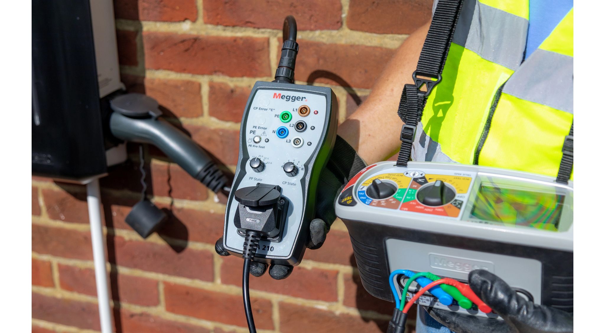
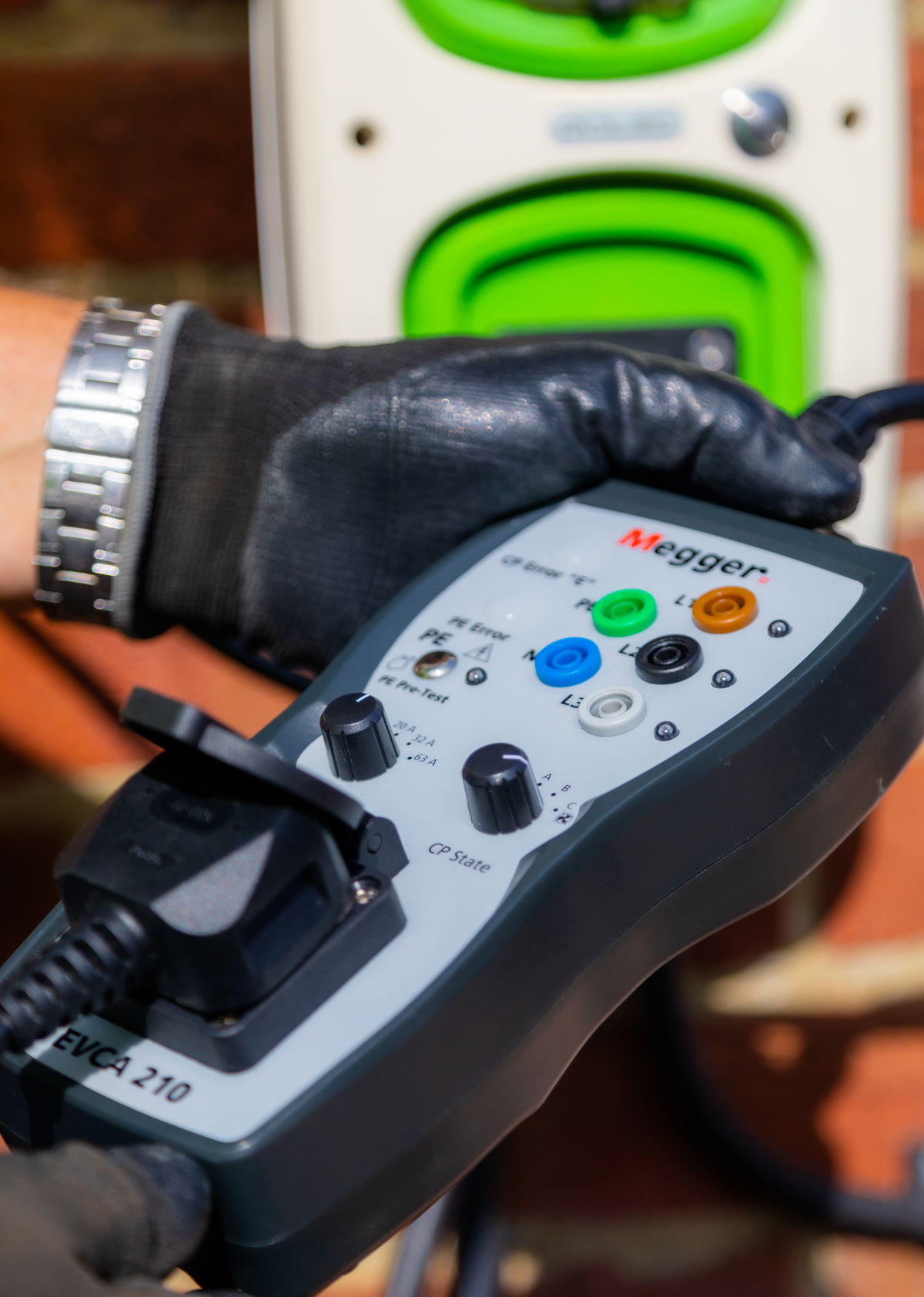
When complete, EV charging point installations must be inspected and tested, using the standard tests prescribed in the IET Wiring Regulations for fixed installations. When these tests have been successfully completed, a full suite of additional tests is recommended. The first is a protective earth pre-test which is carried out before any other testing to confirm that no potential is present on the earth conductor. If this test fails, no further tests must be carried out until the problem has been investigated and rectified as there is potentially a high risk of shock to the person carrying out the tests and to others nearby.
When the protective earth pre-test gives satisfactory results, further tests in accordance with IEC/EN61851-1 and IEC/HD60364-7-722 can be carried out. To minimise the risks posed by working with standard test probes, it is strongly recommended that a suitable adapter, such as the Megger EVCA210 is used. With this adapter, it is possible to conveniently test the functionality and safety of Mode 2 and Mode 3 charging points. Testing in accordance with IEC/EN61851-1 and IEC/HD60364-7-722 is also possible when a Megger MFT1741+ multifunction installation tester is used in conjunction with the adapter, which in this case simulates the connection of an electric vehicle to the charging point.
Further information about the installation and testing of electric vehicle charging points is available from many sources, including a comprehensive guidance note issued by the Electrical Contractors Association which can be accessed via the ECA website (eca.co.uk). The Megger technical support team, which can be contacted at [email protected], will also be happy to answer any test related queries. And, of course, the latest edition of BS7671:2018, The IET Wiring Regulations, should always be consulted when working on electrical vehicle charging points and, indeed, on any other kind of electrical installation.